
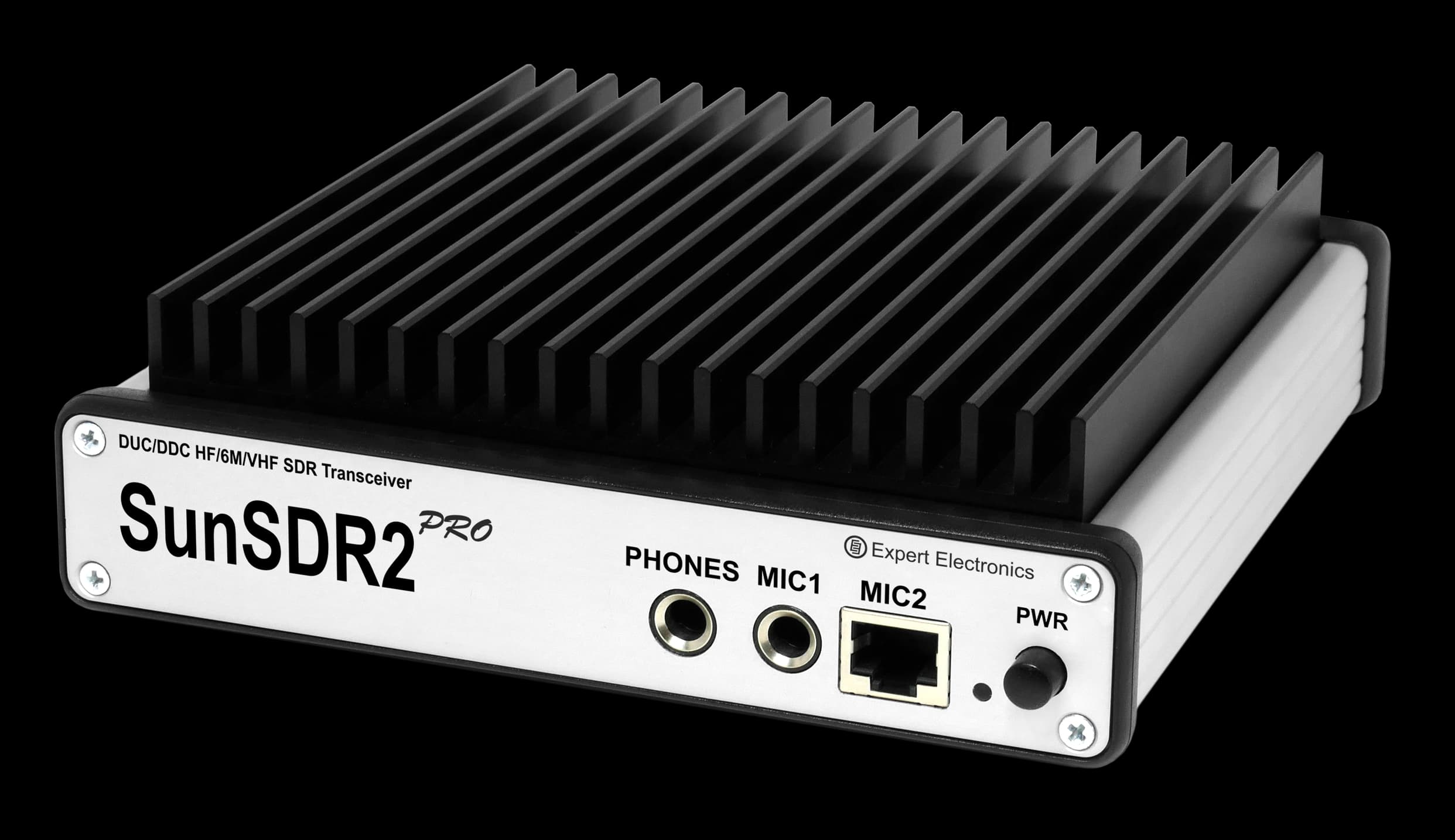
SunSDR2DX PA50WV amplifier
Трансивер с УКВ-усилителем.
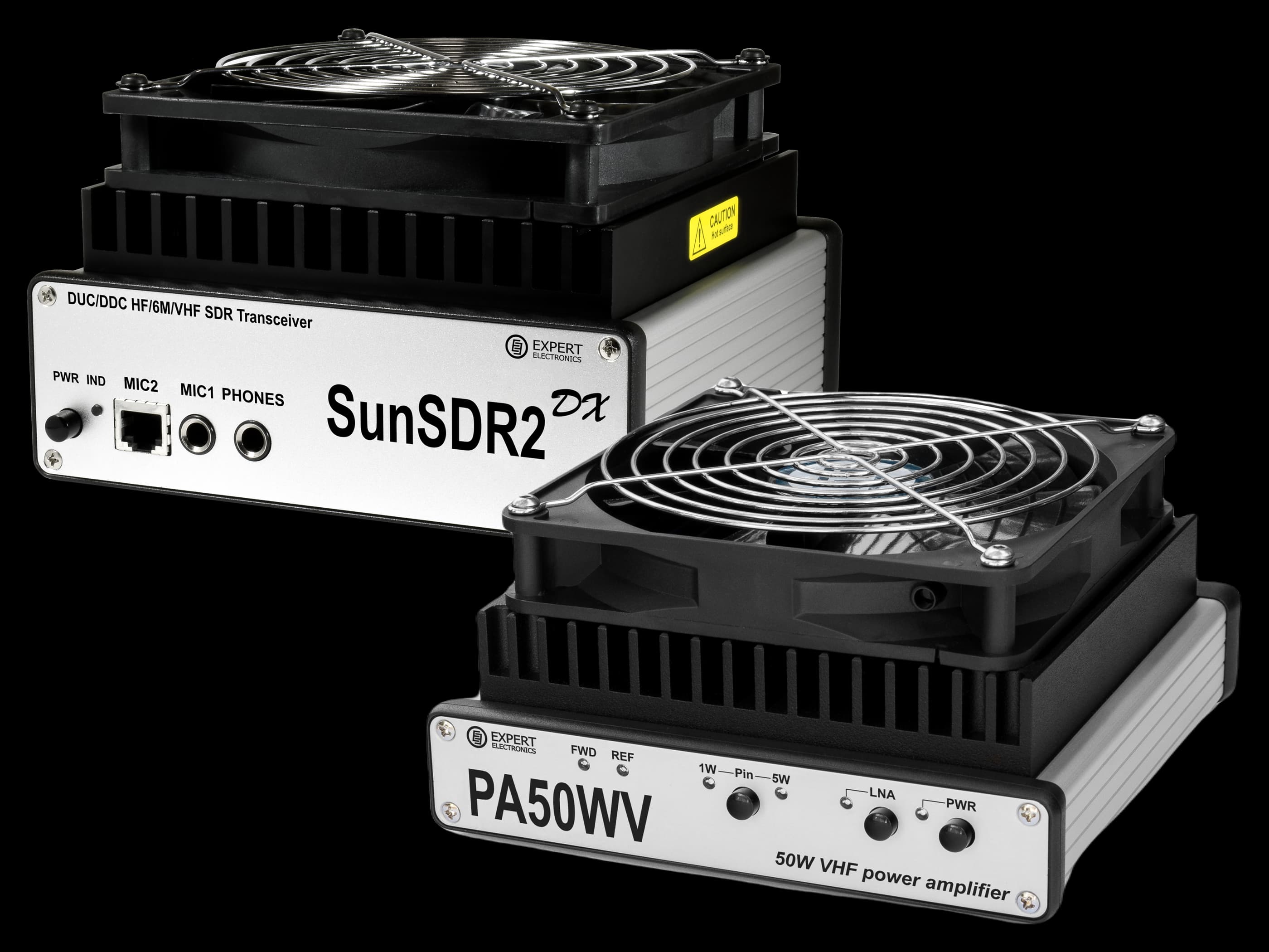
01 / 03 — Bundle — complete set
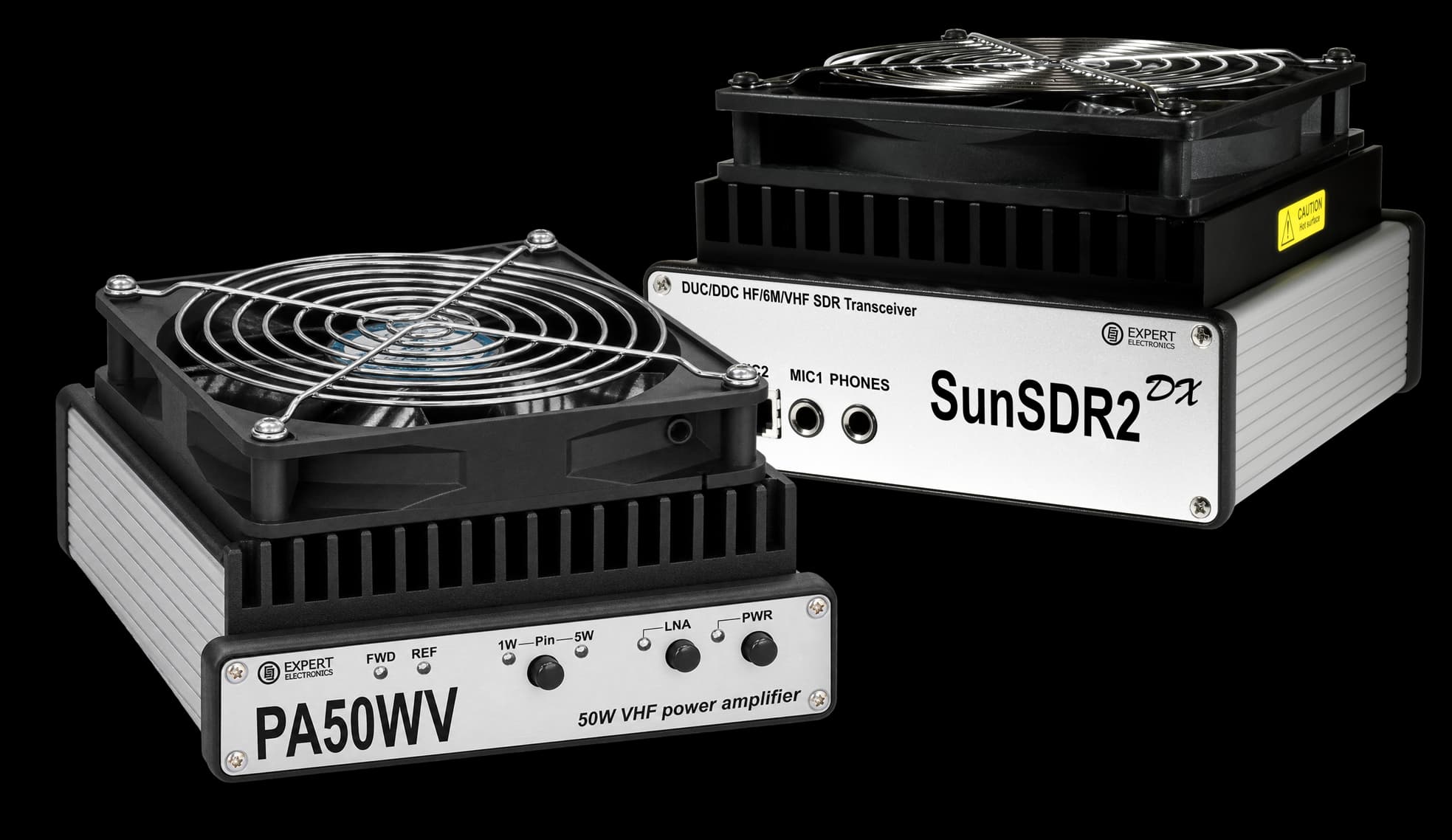
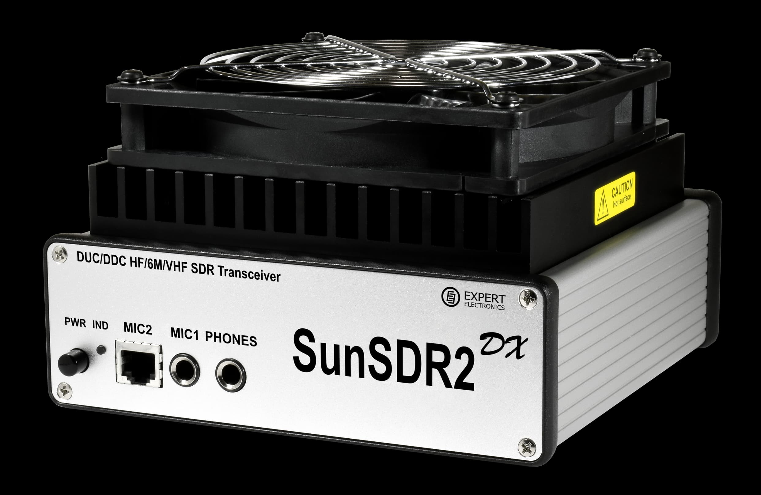
В комплект входят трансивер СанСДР2ДХ и усилитель мощности ПА50ВВ. Основные характеристики ниже относятся к трансиверу.
- HF
- 100W
- ADC
- 16bit
- In bundle
- 2pcs
- 6 m
- 80W
$2,626$2,791
Transceiver features
100 W and a DDC/DUC architecture
- Direct sampling on receive (DDC) and direct digital synthesis on transmit (DUC), with separate receive and transmit paths.
- A 16-bit LTC2209 ADC at 160 MHz: real dynamic range for dense pile-ups and contests.
- A quiet 140 × 140 mm fan and stable operation through long transmit cycles on digital modes.
Two independent receivers
- Two software receivers, each with a sub-receiver; reception 0.1–65 and 95–155 MHz.
- Panorama up to 312 kHz and a band scope up to 80 MHz.
- Simultaneous reception on different HF bands, DX split and an SO2R position with peripherals controlled over ExtCtrl.
Power amplifier
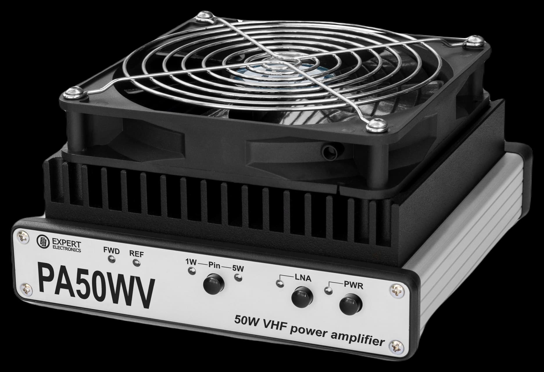
A Mitsubishi RA60H1317M amplifier module is used to deliver 50 W of VHF output power. Active broadband components eliminate the need for adjustment or tuning throughout the operating frequency range. Active cooling allows continuous-carrier operation for extended periods at full output power. The amplifier uses a conventional single-ended circuit and supports all modulation modes.
The amplifier is intended for long-distance contacts on the amateur 2 m band. It can also be used in a vehicle station together with the transceiver included in this kit.
Amplifier features
50 W, 136–174 MHz
PA50WV provides clean signal amplification up to 50 W over the 136–174 MHz range. The amplifier can operate continuously for extended periods, including in digital modes.
1 W or 5 W input
The input-power setting can be switched between 1 W and 5 W.
Dimensions and weight
The amplifier measures 185 × 165 × 83 mm including the cooling module and weighs 1.7 kg, making it suitable for DXpeditions.
Built-in LNA
To improve reception, the amplifier uses a low-noise amplifier with a gain of +19.5 dB. It is enabled by the “LNA” button on the front panel and operates only on receive: power to the LNA is removed automatically when switching to transmit.
LNA in practice
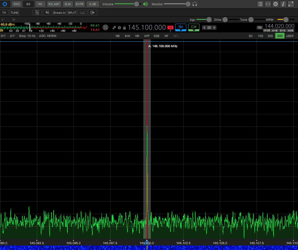
With the TX control input open, the amplifier is in receive mode. The LNA button enables +19.5 dB of low-noise amplification for weak received signals. The LNA is automatically powered down when switching to transmit. Additional receive-path gain applies only in receive mode. If LNA mode is selected, the LNA indicator remains lit during transmit. It shows the selected mode even while the LNA itself is unpowered.
The measurement was made with a SunSDR2PRO transceiver at 145.1 MHz in CW, with a 500 Hz receiver bandwidth and an input signal level of −110 dBm. LNA off: signal −112.2 dBm, noise −122.4 dBm LNA on: signal −93.9 dBm, noise −120.3 dBm The signal increased by 18.3 dB, while the receiver noise increased by only 2.1 dB. The signal-to-noise ratio improved by 16.2 dB: a station that was barely intelligible can now be received clearly. The improvement depends on the antenna, feed line and noise conditions at the operating location: the lower the receiver's own noise, the less an external preamplifier will contribute. These figures are the result of a specific measurement, not a guaranteed specification.
Amplifier control
The amplifier switches to transmit in response to an external control signal from the transceiver through the “TX” connector. PA50WV has no RF detector: an input signal alone does not switch it to transmit, so the transceiver must provide a PTT control output.
The “Pin” button selects an input level of 1 W or 5 W; nominal output power is the same in both settings: 50 W. The amplifier is linear, so output power follows input power: in the 5 W setting, an input of 2.5 W produces approximately half the output power. There is no separate power control on the enclosure and ALC is not used; power is set in the transceiver.
Important. Set the drive-power limit in the “Power correction” menu of the transceiver control software. This sets the maximum output level in the firmware and strictly limits spikes that could damage the amplifier. Never apply an input level above the selected setting.
Amplifier indicators
FWD, REF, LNA and PWR
- “FWD” — the amplifier is transmitting
- “REF” — reflected power; lights when SWR exceeds 3:1
- “LNA” — the low-noise amplifier is enabled
- “PWR” — power
What REF means
The REF indicator is a warning for the operator, not automatic protection: the amplifier does not switch off by itself, so the operator must respond to the indication.
Where it works
- 01
Home station
SunSDR2DX itself operates on HF and 6 m; PA50WV increases transmit power only on the 2 m band, to 50 W.
- 02
Contest position
SO2R/SO2V, split in a dense pile-up, CW skimmer over TCI.
- 03
DX expeditions
Full power in a compact case, from the tropics to the Arctic.
- 04
Digital modes
Reliable operation through long FT8 transmit cycles.
- 05
VHF
2 m on its own, the PA50WV amplifier, transverter support.
- 06
QO-100 satellites
Hardware groundwork for full duplex and transverters.
ExpertSDR3, TCI and ERS
Free ExpertSDR3 with free updates. The open TCI protocol connects loggers, skimmers and digital-mode programs without virtual COM ports or audio cables; programs without TCI use the RadioSync bridge (CAT, OmniRig). Expert Remote System (ERS) is included: control from a browser or ExpertSDR3, directly or through the ExpertCloud service.
About the software- ExpertSDR3Free software for operating on the air
- TCIAn open protocol for loggers, skimmers and digital modes
- ERSRemote operation from a browser or ExpertSDR3
Hardware headroom
ALC*
Input for external power amplifiers; today control runs over ExtCtrl.
Full Duplex*
Full-duplex operation.
Predistortion*
Predistortion for a clean signal without external devices.
* The hardware is ready; software support is planned in ExpertSDR3 updates.
SpecificationsSunSDR2DX PA50WV amplifier
Receiver Characteristics
| RF ADC, resolution | 16 bit |
|---|---|
| RF ADC, sampling rate | 160 MHz |
| ADC type | LTC2209 |
| RX Frequency range | 0.1...65; 95...155 MHz |
| Sub-receivers | 2 pcs |
| Sample rate | 39; 78; 156; 312 @ 24 kHz |
See all specifications for details
Transmitter Characteristics
| RF DAC, resolution | 14 bit |
|---|---|
| RF DAC, sampling rate | 640 MHz |
| TX Frequency range | 160-6; 2 M |
| Output power on HF | 100 W |
| Output power on 6M | 80 W |
| Output power on VHF | 7-8 W |
See all specifications for details
Specifications
| Built-in audio codec / Dynamic Range | 24 / 114 bit/dB |
|---|---|
| RF input/output | 2 HF, 1 VHF (Mini_UHF), ADC IN, DAC OUT (SMA) |
| DC voltage range in RX/TX | 8...14.8 / 10...14.8 V |
| Recommended DC voltage | 13.8 V |
| Current consumption RX/TX | 1.2 / 24 A |
| Power consumption RX/TX | 16.5 / 330 W |
See all specifications for details